Another update on the research going into the new iteration of the Organised Atoms project for the Royal Society of Chemistry. Following the last update where we found it difficult to pin down what exactly happens when we use two cat's whiskers on a single crystal, we decided to backtrack slightly. We don't really need to create a 'known situation' with predictable results or try replicating a transistor. It's more fruitful to take on the spirit of the experimenters from the early days of radio, and use these circuits in a workshop to try and explore this complexity together using sound. Exploring situations we don't already have answers for is key to learning, yet runs counter to how things are taught more generally (and is probably why school is boring for a lot of people).
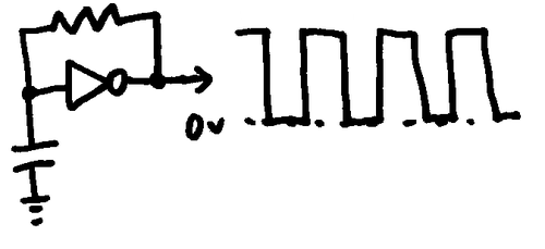
The circuits we've been building so far have all been based on making sounds with square waves: the most basic sounds possible - circuits that turn on and off fast enough to be audible. We use an inverter chip to create these signals, by wiring them back into themselves through a resistor which makes them 'oscillate' from one state to another - flipping a voltage between 0 and 6 Volts. These sound tend to sound quite harsh and 'hollow'.
After searching for more interesting DIY synthesis approaches, we discovered some very clever circuits that use these same inverter chips to create more interesting wave shapes. These take advantage of the voltage at the input rather than the output of the inverter, which - forms a different wave shape, a 'triangle wave' (as it constantly charges and discharges it's capacitor), of rising and falling voltage which we can use to make less harsh sounds.
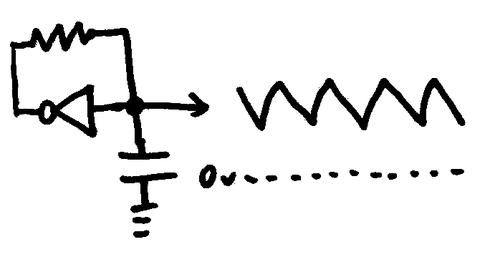
One of the clever things they do which I'd not seen before is replace the resistor in the feedback loop that controls the speed of the oscillation with a diode, which causes the voltage to gradually fall and then "snap" back to its starting point, converting the triangle wave into a 'sawtooth' wave. This is more musically useful than square or triangle, as it forms the basis for a lot of familiar musical instrument sounds - so it generally sounds better to our ears.
What is so exciting about this circuit for this project is that we can replace the diode with one of our DIY crystal semiconductors as it's relatively easy to create diodes with this material. Previously we've found that that these crystals have (at least) two effects on electricity flowing through them, in some places on a crystal the cat's whiskers form a simple resistor, which will form a triangle wave in this circuit, in others it will form a diode (only allowing current to pass one direction) which will tend to create a more sawtooth shape of wave - in theory.
Lets give this a try and see what sounds we can create.
Experiment 1 - oscillator with single point contact crystal (chalcopyrite from Carharrack mine, Gwennap)
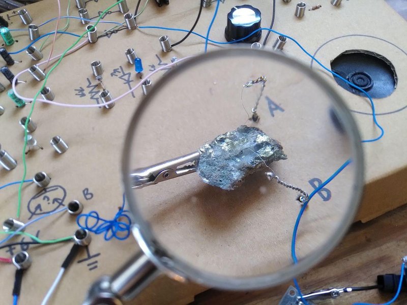
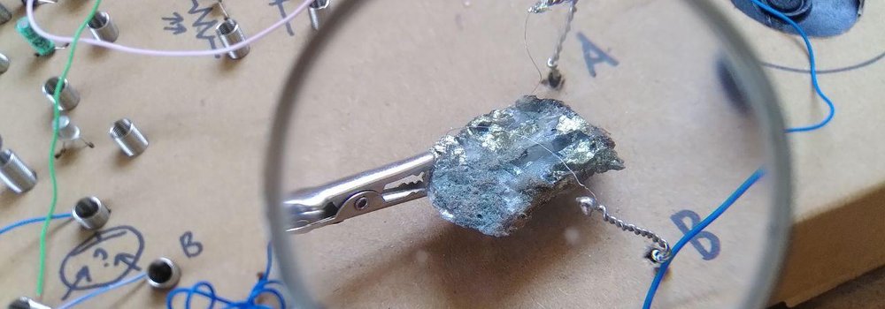
Here we're using chalcopyrite in quartz from Carharrack mine wired up to the circuit - note that we have gone back to using the original crystal holders for this, which are better for experimentation than the new design, even if they are less stable. Chalcopyrite seems easier to use and provide more interesting results than other minerals - but it's the first time we'd tried material from this location before.
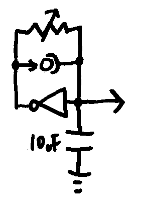
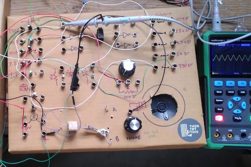
This is the circuit diagram for this test circuit, with the crystal represented as a custom symbol that vaguely represents how it's wired up. We added a variable resistor in parallel across the crystal just to allow us to 'tune in' to a point where oscillation was occurring best. We know from our curve tracing of pyrite and similar minerals that the voltage/current relationship is very bumpy and non linear, so it's not surprising that the results are chaotic - but it's quite simple, as we only have a single oscillator. This is, however the simplest way we've found so far to hear what happens when we pass voltage across a naturally grown crystal.
These recordings are made with no interaction with the crystal or circuit - so any noise, sudden changes or shifts are 'natural' in that sense. This contrasts with circuits without a crystal which extremely stable.
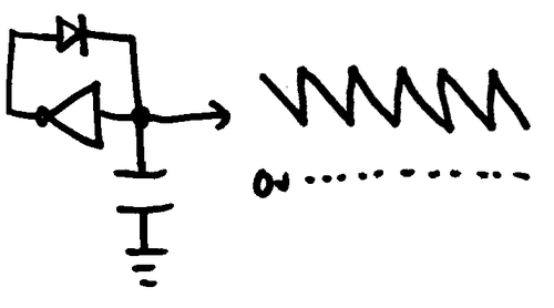
Experiment 2 - adding another oscillator and using a second point contact
Here we get a bit more complicated, but still well within the range of being able to build it on our cardboard synth in the workshop.
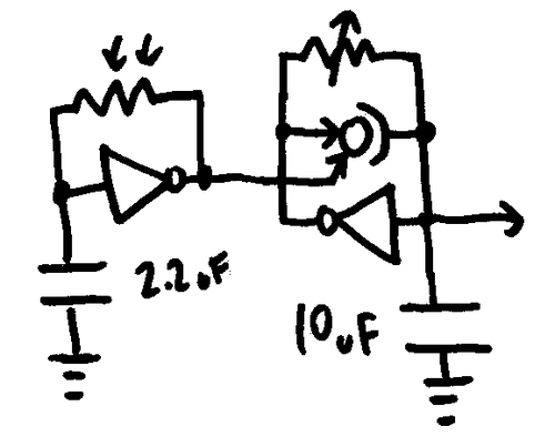
Keeping the same circuit on the right, we build another square wave oscillator on the left - and send it's output to the other cat's whisker to 'perturb' the crystal while it's being used to shape the second oscillator. This results in more interesting interferences.
From these simple tests it's going to be much easier to create smaller, more interesting circuits that are less hassle for people to build. This means we can introduce the crystal earlier on in the electronics part of the workshop, and gradually make more complex sounds with them. Some people will be happy to just build a few of the simpler circuits, while others will to want to try the most complicated ones first - we'll design the workshop so the families can go at their own pace, and combine this with smashing rocks, fossicking for minerals and using more traditional means to identify what they've found using visual identification, scratching against a stock of known minerals, and streak colours on unglazed tiles.
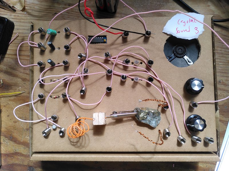
This is the new box, designed with these experiments in mind, we've started collecting photographs (like patches in modular synths) to record good circuits with a little name tag. This means we can go over these afterwards and convert them into wiring diagrams for the workshop.