In recent months, we have been developing and testing our SmogOff air pollution sensor. Our first prototypes were housed in generic weatherproof enclosures, with the sensor components sitting inside pipes attached to the top of the boxes (see image below).
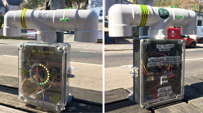
For this simple version of the SmogOff we used polycarbonate enclosures (like this enclosure used for the Sonic Kayak project) and plumbing pipes (we used FloPlast pipes; one ‘tee’ and two ‘bends’ for each housing) fixed together in a t-shape, with the openings facing downward to protect the sensor components from rain. The tee pipe was glued to the enclosure with epoxy resin. One of the bends was glued to the tee pipe with epoxy resin, while the other was fastened with cable ties and tape to make it easier to position the sensors in the pipe during setup. A hole was drilled in one end of the enclosure to allow cabling to be fed through from the enclosure into the pipe. We also drilled holes in the sides of the enclosure so that we could screw on stainless steel eye plates to allow the unit to be attached to fencing/lampposts. Silicone was applied to the eye plate bolts to stop water getting into the housing. Finally, a small piece of wood was glued to the inside of the enclosure, which the Arduino was fixed to with screws.
Cloud design
The plumbing pipe version worked fine, but we wanted to design and make a dedicated housing for the SmogOff sensor. In June, I spent two days with Aaron Moore at CNCCraft, for training in digital manufacturing and to develop ideas for the design of the SmogOff housing. I brought along a few initial ideas and sketches for a cloud-shaped housing with me as a starting point, then Aaron and I sat down to discuss various aspects of the design, including which materials to use, how to ensure airflow over the sensor components, and ways to weatherproof the housing in order to protect the electrical components from damage.
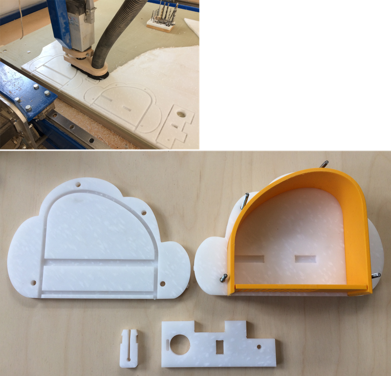
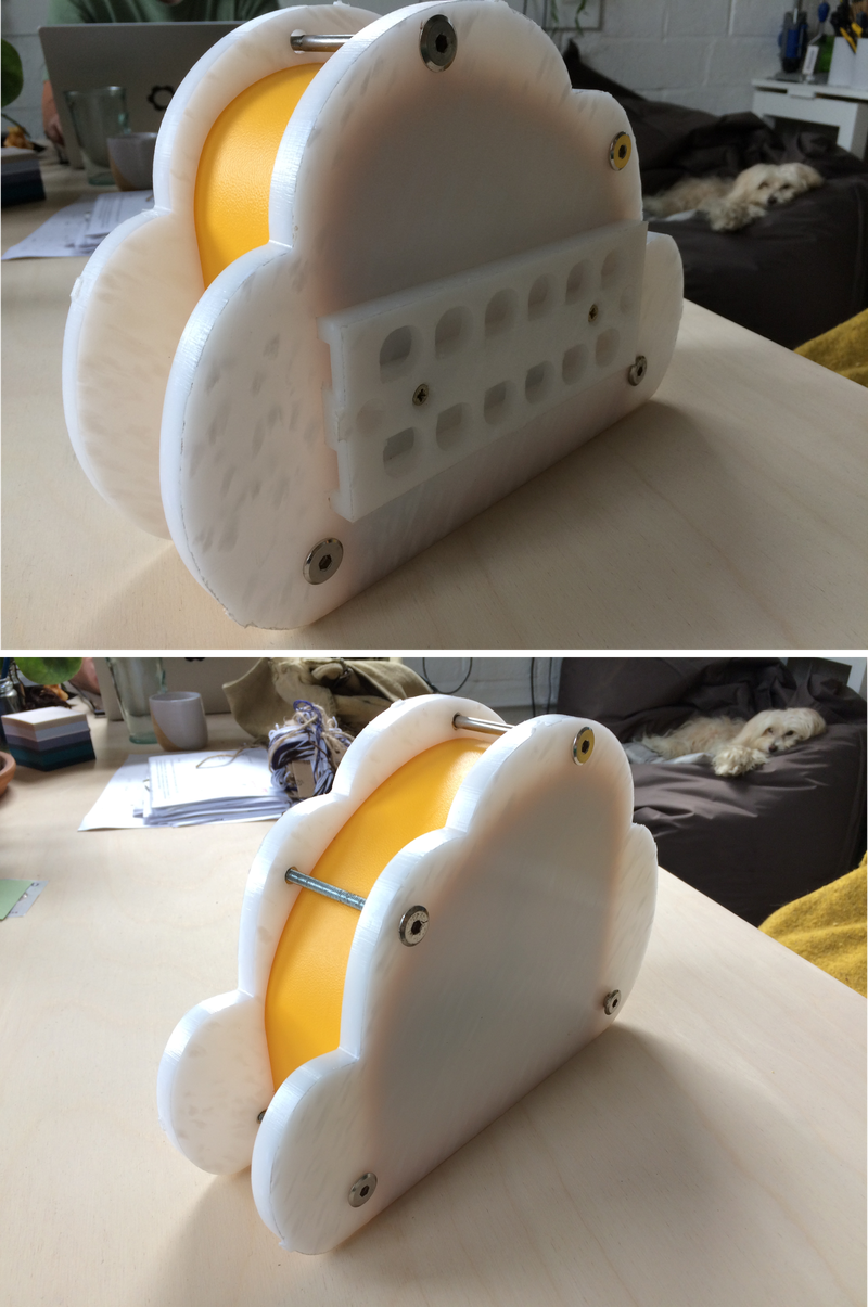
This led us to our final design, which consisted of two cloud-shaped panels, separated by a curved canopy covering the internal electronic components. We also incorporated a shelf to hold the sensor components and battery in place, as well as a section at the base with holes to allow airflow over the sensor components. The front and back panels had grooves to allow the components to fit together neatly. Initially, we wanted to make the housing out of recycled plastic.
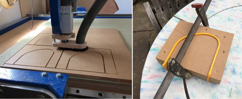
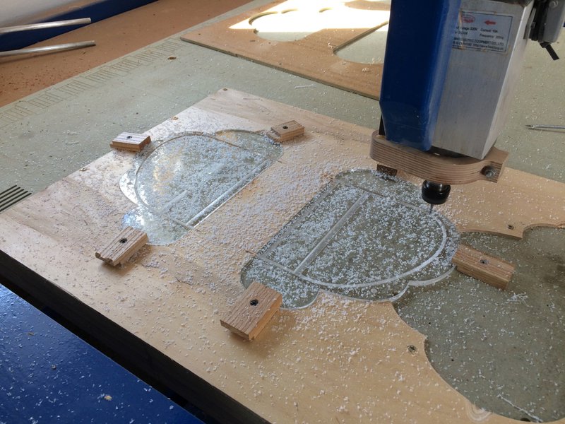
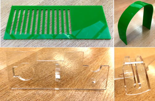
We drew up each of the individual components in open source CAD (computer-aided design) software (LibreCAD). We then used Aaron’s CNC (computer numerical control) router, a computer-controlled material cutter, to machine the components from medium-density fibreboard (MDF) as an initial test. The CNC router can be programmed to cut at different depths (e.g. cutting all the way through, or machining shallower grooves in the material).
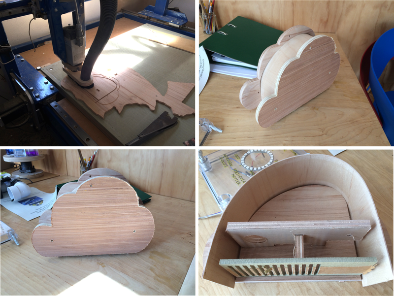
After assembling the test version of the housing, we made some small tweaks to the dimensions of the components in the CAD software and began making a version out of recycled plastic.
While most of the components were machined from flat pieces of material using the CNC router, we needed to bend a sheet of plastic to the correct shape for the canopy section. To do this, we used the CNC router to cut out blocks of MDF which we stacked on top of each other and screwed together to make a mould. We then heated a sheet of plastic in the oven until it could be reshaped, before clamping it between the blocks and allowing it to set in the right shape.
We cut out the rest of the components with the CNC router; the cloud-shaped front and back panels (with holes to allow them to be screwed together), the shelf to hold the sensor components in place, and the bottom section.
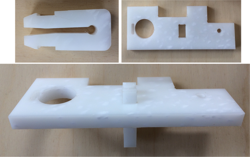
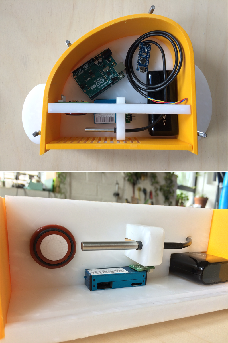
Below shows the shelf section in more detail. Aaron had the great idea of holding the temperature sensor in position with a flexible clip (also machined with the CNC router) that slots into a hole in the shelf.
The image below shows the bottom section with holes to allow airflow over the sensors.
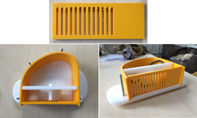
The picture below shows how the components sit inside the housing. The cut-out sections in the shelf allows the PM and NO2 sensors to sit in the correct position.
We also CNC-routed a mounting bracket which we screwed on to the back of the housing. This was added to allow the sensor to be easily attached to lampposts/fencing. We designed and cut this mounting bracket very quickly, and it required adjustments to make it easier to thread cable ties through and to improve stability of the unit when attached.
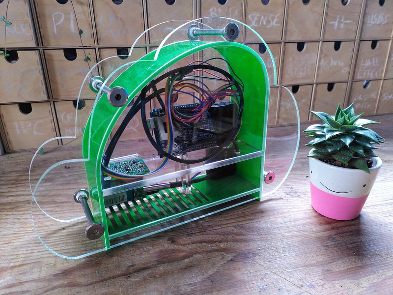
Acrylic version
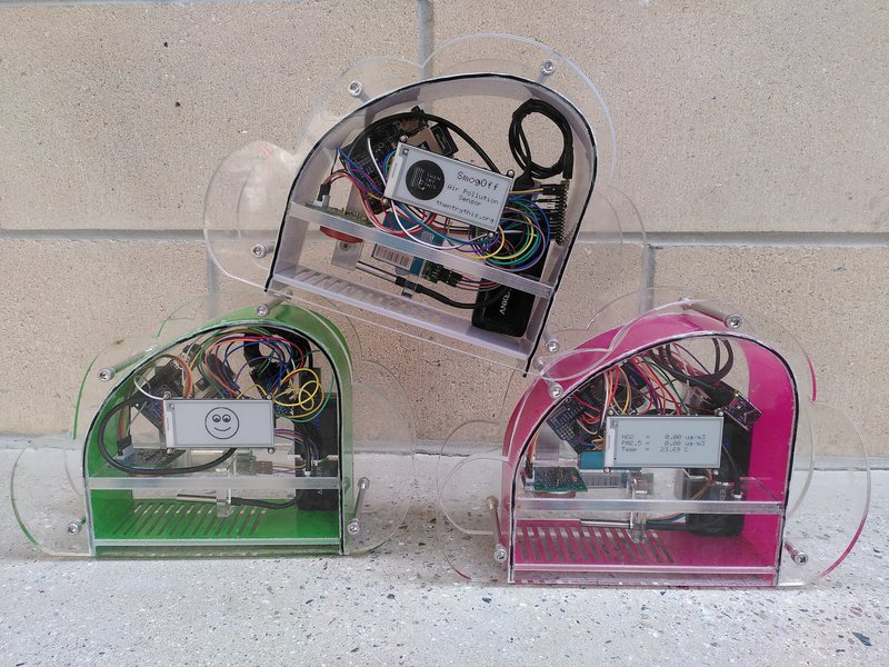
We were kindly given some additional funding from BBSRC, which allowed me to spend four more days in August and September working with Aaron on refining the housing design. We decided to make the final version from clear acrylic rather than the opaque plastic we used for the previous version. There were practical reasons for this decision; being able to see inside the unit is useful for checking whether the unit is turned on and working properly (e.g. can see lights flashing, how much battery power remains etc.). Being made from clear acrylic also made it a lot easier to add a screen to display real-time data visualisations. We also thought it made the unit look much more interesting, as you can see the internal sensor components and circuitry.
For our first attempt at an acrylic version, we used 6mm-thick clear acrylic for the front and back panels (with 3mm grooves), the shelf, and the clip for the temperature sensor. We used 3mm-thick colour acrylic for the canopy and bottom sections. We made some changes to the designs in the CAD software to account for the changes in material thickness since the opaque plastic version and added a small cut-out section in the shelf to allow cables to be fed through from the PM sensor to the upper compartment.
We initially used the CNC router to cut both the outline of each section as well as the grooves. However, we found it to be quite tricky using the CNC machine to cut acrylic, because it has a tendency to melt and stick to the drill bit, which results in a rough finish. We found that spraying WD-40 on the acrylic as it was being machined helped prevent this. We also found that the finish could be improved by adjusting the spindle speed (the speed at which the drill bit rotates) and feed rate (how fast the drill moves across the material). We found that a spindle speed of 300 rpm and feed rate of 1500 mm per minute produced the best results. We also bought a specific drill bit for cutting acrylic (a ‘spiral upcut flute’ shape which throws debris upwards and out of the hole/groove being machined) to further improve the finish.
However, in the end we decided to laser cut all of the components, which we found gave the edges a nice glassy finish, and only used the CNC only to machine the grooves for the front and back panel. In order to cut grooves into the laser-cut front and back panels, we CNC-routed a wooden template which held the acrylic in place on the bed of the CNC machine.
Before we made a final version, we wanted to incorporate into the design a rubber seal in the outer grooves of the front and back panel, to prevent water getting into the housing. We bought some 2mm diameter nitrile rubber o-ring cord and decided to use slightly thicker clear acrylic (8mm) for the front and back panels and shelf, to allow for deeper (4mm) grooves that would accommodate the width of the rubber cord while still allowing the other components to sit comfortably in the groove. We made some tweaks to the dimensions of the components to account for the new material thickness and groove depth.
For the canopy section, we heated the 3mm acrylic to about 130॰C. We found that too much heat causes the edges to go out of shape when in the mould, while not enough heat makes it difficult to bend into shape.
We added silicone to the outer grooves in the front and back panel to fix the rubber cord in place. The rubber and silicon compress when the unit is bolted together, which creates a watertight seal.
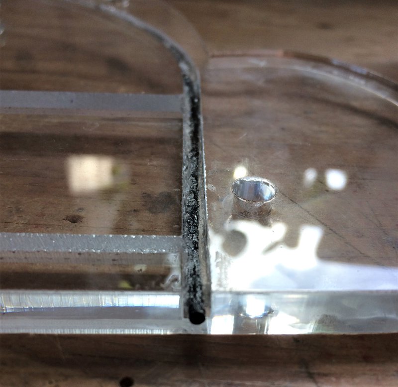
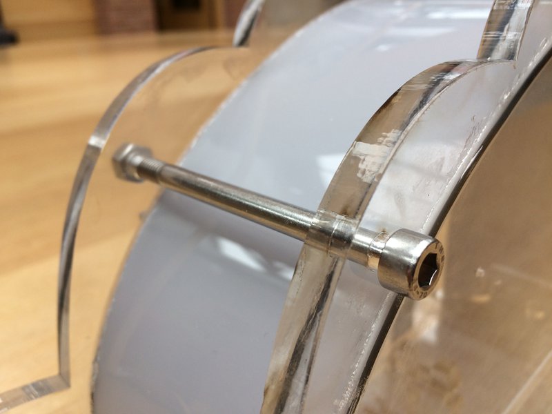
The front and back panels had laser cut holes (6mm in diameter) to allow the housing to be bolted together. We used 90mm M6 marine grade stainless steel bolts and hexagonal nuts to hold the unit together.
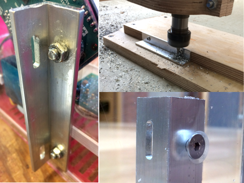
For the final version, we improved the design of the mounting bracket, opting for a sturdier aluminium design. These brackets were made from a length of aluminium equal angle (approx 20mm x 20mm x 3mm). We cut them to size and machined holes in them using the CNC router (see image). We drilled holes through the back panel and used countersunk M5 screws so that the bolt heads lay flat against the inside of the unit. Silicone was applied to the screws to stop water from getting into the housing.
We drilled four small holes (approximately 3mm deep) on the inside of the front panel, so that a screen could be attached to the inside of the housing.
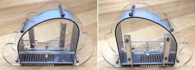
Final product
Below are pictures of the final product, with and without the electrical components. All CAD files for the SmogOff housing can be found on the Gitlab page for this project.